
A Portable Layout in S-Scale
The S-Size, Dual-Gauge Zilwaukee
Okeechobee and Tremungus
- - Power and Wiring - -
| Home |
|
|
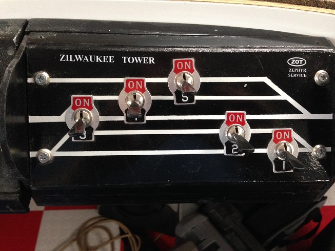
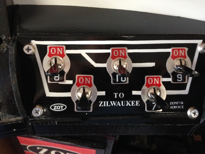
| Block Shut Off Panel - Passenger Station These switches are used to disconnect one rail (center rail for O-Gauge, outside rail for S) for the 4 double-ended passenger tracks and one additional stub located just outside the station building and parallel to the other tracks. | Block Shut Off Panel - Mainline and Storage Spurs These switches are used to disconnect the outer O-Gauge stub and the two halves of each of the mainline loops. The idea is that there can be two trains in the station and a third in the remote stub. Then, to bring a train out from the stub, and place one of the trains from the station, one half of a mainline loop can be used for temporary storage. No shut off switch is required for the power to the remote S-Gauge spur. Since power to it is automatically routed by the extra contacts on the Tortoise switch motor. |
|
|
|
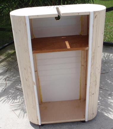
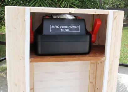
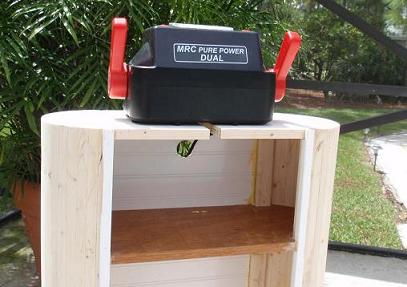
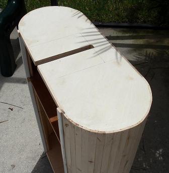
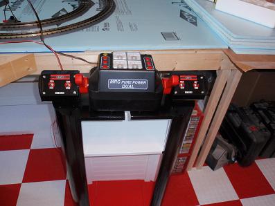
| Power Tower 0 This is one of two transformer stands. It is made entirely from scraps left over from finishing the interior or the shed and making the bench work. It is mounted on the rollers from those plastic drawer sets. The drawers are handy, but the casters always break the plastic and fall out. They won't do that to the 3/4-inch bottom. You can see the hole in the back for the wires and the slot in the top. | Power Tower 1 Here you can see the transformer in its storage position. When it is on that shelf, the whole thing fits under the benches. The slot allows the wires to be stowed as well without disconnecting anything. These transformers have plenty of power, meters and three circuits: two throttles and one for accessories. | Power Tower 2 This photo shows the transformer in operating position. In this view, the only wires are the power cord. Soon, there will be 6 more. Two will be for accessory power and the others will be connected to auxillary panels. These panels are explained below. |
|
|
||
|
|
|
| Power Tower 3 Here is a view of the top of the stand showing the slot that assists in keeping the wires neat in operation or when stowed. | Power Tower 4 Here you can see the final colors. The bottom is covered with some spare floor tiles. Cutting those to fit was a bigger challenge than I expected. You can also see the relative position of the two auxillary panels. | Power Tower 5 This self-portrait of my hand shows how the auxillary panels will be mounted on the front of the bench work. Actual mounting will wait until after the fascia is installed. |
|
||
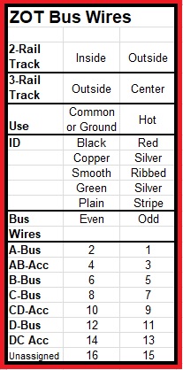
| ZOT Bus Wires I used stranded wires salvaged from a variety of sources. This little card was printed on heavy, card stock and kept handy during installation and any maintenance or trouble-shooting. Saves a ton of time. | ||
|
|
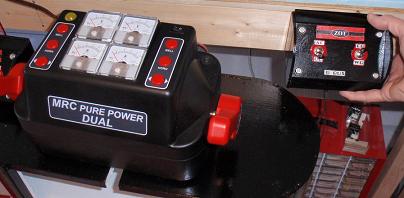
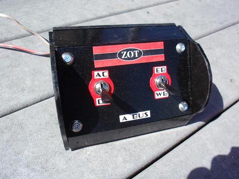
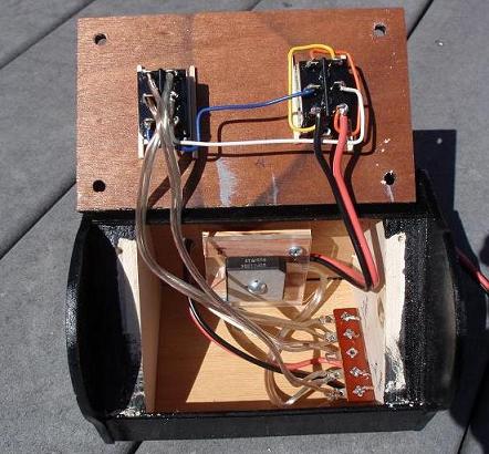
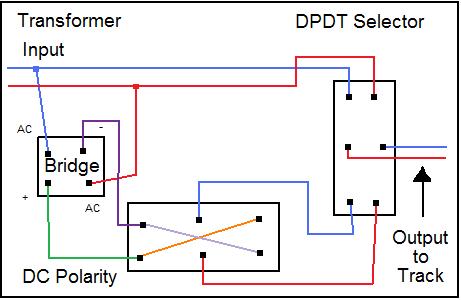
| AC DC Selector 1 These little panels are used to choose whether the throttle will provide AC (as it was made to do) or DC (as I sometimes require) If DC is selected, the second switch for direction comes into play. I arbitrarily labelled one direction as East Bound and the other as West Bound. The switch labels were made by painting the original plates red and then attaching home made labels. That Zephyr font adds to the fun. Since there was space, I also pasted on a ZOT logo. | AC DC Selector 2 The switches and the rectifier bridge are heavy duty items. They need to handle the potentially high current that might occur before the circuit breaker in the transformer shuts it down. Some older locos, lighted cars and double-headed consists can draw a bunch of amps in normal use. These components are rated 10 amps. |
|
|
|
|
|
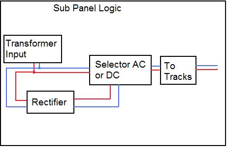
| Sub Panel Logic | Sub Panel Schematic |
|
|
|
|
|
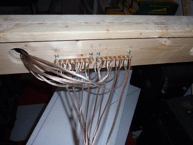
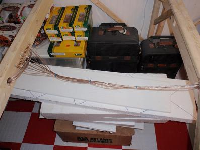
| Power Bus 1 Here is a view of the power bus and terminal strips. These strips are mounted all around the layout and wired before anything else. I know I will need them, eventually, so I put the wires while I can reach everything comfortably. My grandson helped and learned something about soldering in the bargain. The wires I used are 18 gauge speaker wire. That stuff is not expensive and is available at the big box hardware stores in reels. | Power Bus 2 This view shows the cables as they are routed from one terminal strip to the next. After placing them, We applied cable ties to keep it as neat as we could. One thing to remember is to keep close watch on which wire goes to which terminal. Later on, it will be tough to find a problem, so, I keep a notebook, define some standards and test, test, test at the start. I am never sorry I took a few minutes at this stage to avoid hours of difficulty in a couple of years. Some these wires are (like the ones shown) in different colors (silver and copper). Some have ridges on the insulation of one wire and are smooth on the other. Keep notes and live with your own, defined standards. You will not be sorry you did. |
| Home |
| Site and Pages Copyright 2011-2025 - William P. Porter --- Some content belongs to the indicated provider. |