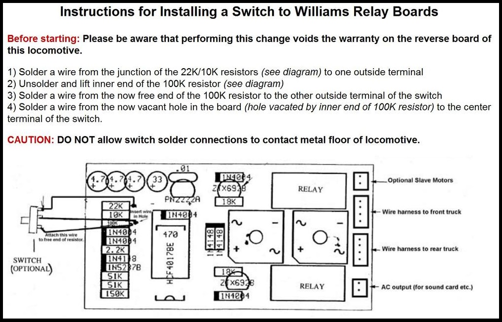
This plan is provided on the Williams by Bachmann site.
|
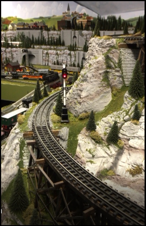
| A friend of mine has a large O-Scale layout. I helped build it.
One level has a long continuous loop. I divided it up into electrical blocks and added a
board full of relays to allow automated operation of two trains. As a train enters a block,
it trips a relay to cut power to the block behind it and activate the signals. If the
following train gets to that block, it stops. When the front train moves beyond the control
block, power is restored. The train that had been paused resumes its journey. That all requires
locos to be locked in forward only running. He has a Williams Amtrak loco which does not
have the lock out. So, I found this information on the Williams by Bachmann site. It is
delicate soldering work to lift the end of one resistor and attach three wires to a
SPDT slide switch. Easy if we are careful. Works like a champ. Slide the switch one way, the trains runs
forward only. The other way and the 4-step reverse unit works normally.
|
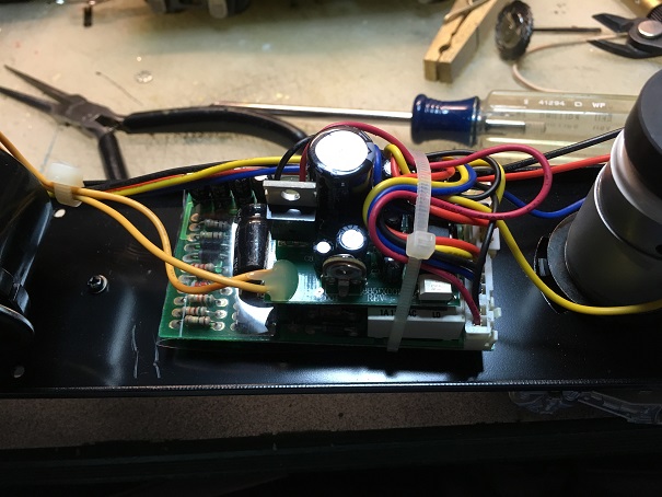
Two circuit boards tied together in the Williams loco
|
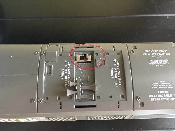
The switch is mounted in the roof of the loco shell
|
| The Williams original installation has two circuit boards that are tied together with double-sided foam tape and
secured with a cable tie. The assembly is further insulated from the metal chassis with a piece of clear plastic. Then, there
is a screw through the bottom board (reverse unit) to the chassis. Nip the tie. Gently pry the two boards apart. Remove
the screw. Have some two-sided foam tape and a new cable tie ready for reassembly.
|
A simple way to mount the switch is to grind out a rectangular hole in the top of the loco shell as seen here. The switch
is secured to the shell with super glue and some blobs of hot glue. If you have a 3D pen that writes with PLA filament.
That would be stronger than the hot glue. It might be better to grind the hole in the metal chassis facing the bottom. When
train manufacturers do this sort of thing, the holes are punches as a part of the normal fabrication process. Very neat.
Not so easily done as a hobbyist modification. In this case, I aligned the switch so that when it is in the forward position,
the loco will only run forward. In the rearward position, the normal revese unit, 4-step sequence works.
|
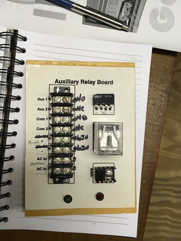
Relay Board
|
Block Control Video
|
|
This picture shows the relay boards. There are three of these, one for each set of electrical blocks. The graphic
is printed from a spreadsheet program. The cells in that spreadsheet are sized to match the spacing on the terminal strip. Power
for the relay is passed through a typical accessory arrangement. One outside rail is cut at both ends of teh control block. The
power for the relay passes through that rail, back to the ground on the other rail when a wheelset enters the block. Since the
relay I used is DC, you can see the bridge rectifier and voltage regulator (mounted on a heat sink) parts as well as the relay.
When a set of wheels is in the control block, the relay is activated. That disconnects the center(hot) rail in the controlled block
and tells the signal to turn red. If the following train enters that controlled block, it stops. When all of the wheels in the
leading train leave the control block, the relay is deactived, power returns to the controlled block, the signal is set to green.
Any stopped train restarts. That is why the locos must be set to run in forward only.
|
This link takes you to a short video on YouTube. It shows the block control in action.
Use the Back button on your browser to return here.
|