
A Portable Layout in S-Scale
| Home |
The S-Scale Zilwaukee
Okeechobee and Tremungus
- - Benchwork and Basic Wiring - -
Overall View of the North West Corner
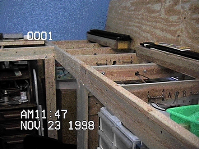
The front and back edges are L-girders. The support legs are made from 2 pieces of 1x4 glued and screwed into an angle. Overall, there are 7 benches. Each is free standing with its own four legs. The underside of each bench top is 47 1/2 inches above the floor. Bus wiring consists of 16 wires - 8 circuits. Terminal strips are placed every 2 to 3 feet. All of the terminal strips and the bus wires were soldered in place before any track supports were added. Two pairs of wires are for the DCC - primary and secondary. Another pair is for turnout motor power. The remaining 5 are for lighting and accessories. By wiring these power buses up front, the detail wiring later will be simple for each case.
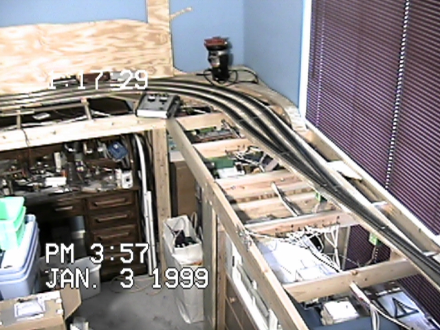
Staging Tracks - View 1
Here are the three, hidden staging tracks. The view is towards the South West corner. These tracks will be hidden by scenery and other trackage. The plan is to have three long trains or up to 6 short ones stored in here, ready to make an appearance during an operating session. The turnouts are number 8 and each is operated by a Tortoise motor. The plywood leaning up against the west wall is for the car ferry area. It will be installed on short risers after the mainline track is in.
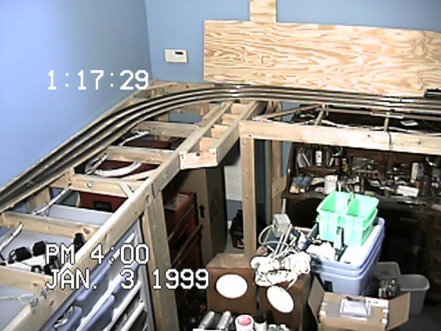
Staging Tracks - View 2
Here is the North-West corner view. It shows the continuation of the staging tracks. Two have lengths of 15 feet (between the fouling points) and the outside line is about 3 feet longer. You can also see the completed bus wiring and the temporary switch motor controls. The American Flyer caboose in the far corner was recently acquired. It will be converted for use on the code 100 track. It is sitting on the router used to cut the turnout throw holes. There will be a turntable in that area, but, it will rotate just a touch more slowly.
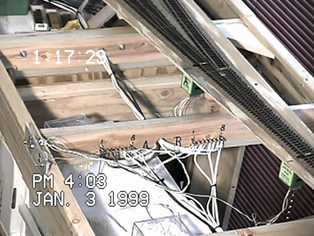
Staging Tracks - View 3
This closer view shows the terminal strips for the bus wires a little more clearly. I used heavy lamp cord for most of the bus wiring. Eventually the motor controls will be DCC decoders rather than DPDT switches. The plan calls for no control panels - just operation using the handheld controllers. Time will tell.
The nest step is to add the mainline trackage.
| Home |
| Site and Pages Copyright 2011-2025 - William P. Porter --- Some content belongs to the indicated provider. |