
A Portable Layout in S-Scale
The O-Scale Gator Lines
of Frank Gillette
- - Early Trestle Work - -
| Home |
Here are a set of photos of the three, large, wooden trestles and bridges from the O-Scale layout of Frank Gillette. They show the locations at which the trestles will be installed and some of the construction progress on the structures. There are three elevated tracks. All are supported with trestles. All have a bridge of some sort that is integrated with the trestle.
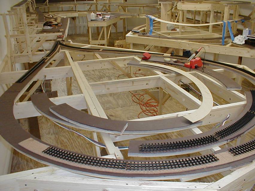
In the foreground, you can see the location for trestle #1. It is the longest trestle of the three. In the center of it, there will be a bridge over a road leading into the elevated town. In the background, you can see the locations for trestles #2 and #3. Trestle #2 will be fitted into the gap in the middle level track. At one end of the span, there will be a large arch bridge. Trestle#3 is similar to trestle #1 in that it has a bridge over a road near the center of it.
In all three cases, we cut a pair of templates out of door skin plywood. It is economical, flat and about 1/8 inch thick. One of each pair was kept here in the layout room to assist in aligning the track as the supports are installed. The other template was used at the 'trestle fabrication factory' to assure that the trestles would fit the spaces allotted.
Here is another view showing the locations of trestles #2 and #3.
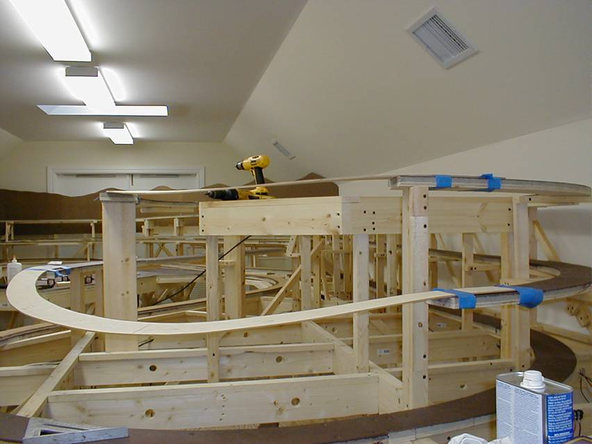
Here you can see the middle-level trestle (#2) template has been taped to the track supports. Our intent is that the actual trestle will not have quite as much dip to the road way when it is completed. The template for the high-level (#3) trestle is visible edge-on. The drill is behind it. The ground contours will rise sharply from the lower level to the upper level at this point. So, the trestles will each be about the same physical height above the ground where they are located.
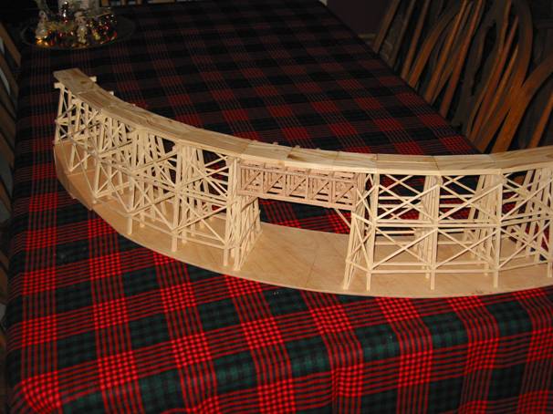
This photo shows trestle #1 as it was before the entire thing was stained.
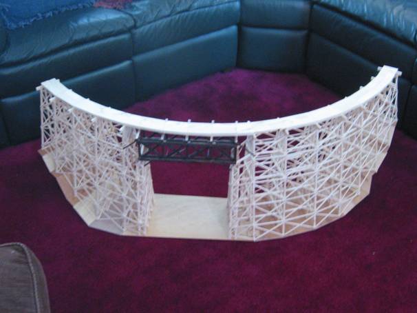
The center bridge section will span a road for automobiles. That section was made from oak. The rest from 2x4 lumber. All of the wood was cut to the appropriate scale size using normal shop tools and a hobby-size table saw. The bridge members were stained before assembly. That turned out to be a bad idea. The stain inhibits the carpenter's glue from making a strong bond. At one point, the bridge was dropped to a hard floor and re-kitted itself. That is, the glue joints mostly let go and the thing became a pile of nicely stained, oak sticks.
For the second assembly of the bridge section, I sanded the areas where the glue would be applied. I also drilled holes at most of the joints and inserted brass, escutcheon pins for increased rigidity. Those steps resulted in much more stability.
| There is another page that shows more details on the construction of this trestle - #1. |
This is a photo showing the Arch Bridgethat is placed at one end of Trestle #2. It is used to carry the middle level track across some tracks from the lower level. Since it is supporting a curved section of track, the bridge is much wider than it would be for tangent track.
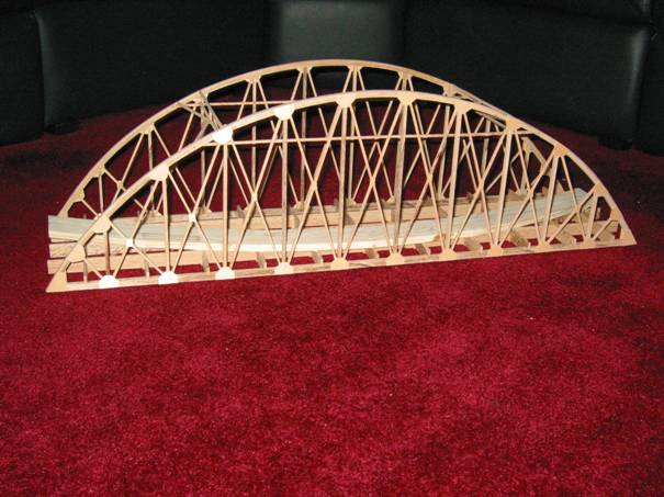
The arches, truss pieces, upper sway braces and the 'egg-crate' main deck are all made from oak. Standard ľ inch stock was ripped on a radial-arm saw and then ripped again on a hobby-size table saw to produce the lumber required. The arches were made from several 1/16 inch thick pieces that were soaked and then clamped to shape until they dried. After that, they were laminated using carpenter’'s glue.
The gussets were made from maple veneer that was cut to size on a hobby-size table saw.
The roadbed was made from stock 2x4 lumber that was ripped on a radial-arm saw and cut to size using a smaller, table saw.
In this view, the upper sway braces have not yet been installed and none of the wood has been stained to the final color.
Here is a view of trestle #3 before it was stained.
This trestle has a central bridge that spans a road just as does trestle#1. This span was also made from oak, but, it is of a different design than the other bridge section. It uses smaller lumber and more sticks with no escutcheon pins. It was assembled and glued before staining. The rest of the trestle was also made from cut-down 2x4 lumber.
This trestle is positioned for the high-level track. At this point in the layout, the ground contours rise a bit, so, the high-level track requires a lower trestle than does #1. After this picture was taken, we decided to add elevating risers to the plywood base. It takes the form of a box structure that will be below ground level and can be attached directly to the benchwork. We also applied a sloped base for the automobile road that passes below the bridge.
Here is a short video survey of the Alachua Central as it existed in April 2011.
| Home |
| Site and Pages Copyright 2011-2025 - William P. Porter --- Some content belongs to the indicated provider. |