| Site and Pages Copyright 2011-2025 - William P. Porter --- Some content belongs to the indicated provider. |
| Home |
The S-Scale Zilwaukee
Okeechobee and Tremungus
- - Mainline Track - -
Main Line Track on the New ZOT in S-Scale
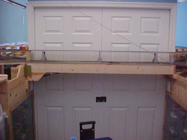
Photo 1 - The doorway swing bridge
Entry to the train room is by way of a pair of pocket doors. The track plan runs around the walls. I prefer to have no duck-unders. So, this section of the layout is mounted with a hefty door hinge. It is about five feet long and I could find no hinges that were strong enough to support the weight. The chain provides some relief although it is visually unappealing - compromises are required.
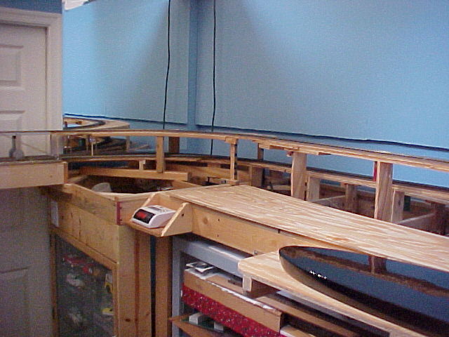
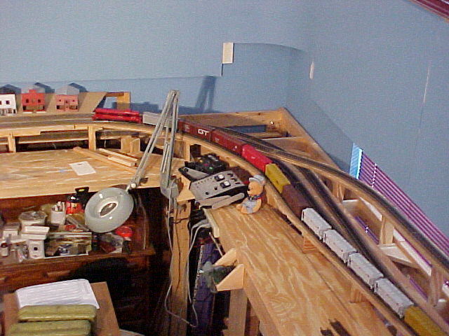
Photo 2 Bridge Tracks - View 1
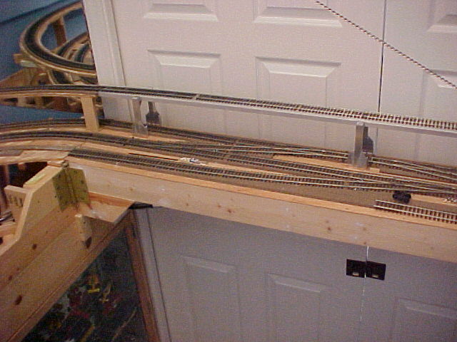
On the swing bridge are the tracks that complete the loops and provide access to the car ferry and engine service facilities. The main line track runs around the room twice in an over and under configuration. The actual crossing takes place here on the swing bridge. Also on the bridge the hidden staging tracks connect with the main line and complete their own, independent loop. Finally, the lead for the car ferry and the rest of the wharf area breaks off from the main line on the bridge. This view shows the north end of the bridge. The following view shows the south end.
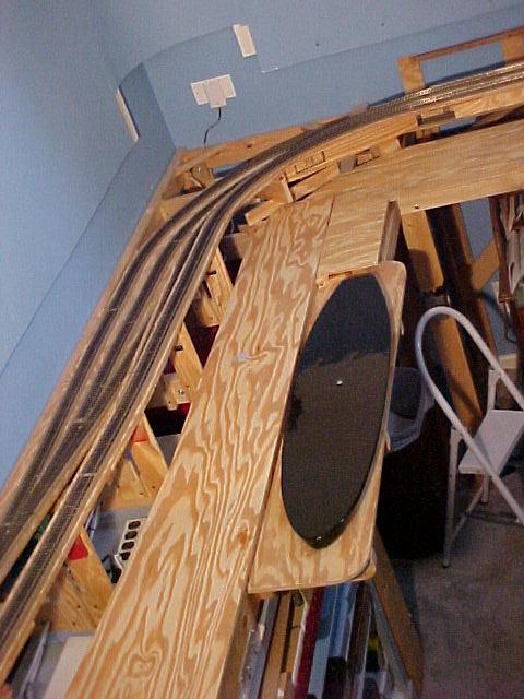
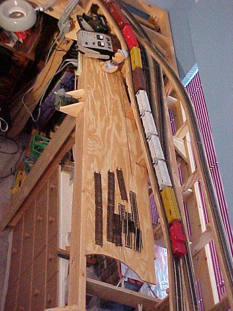
Photo 3 Bridge Tracks - View 2
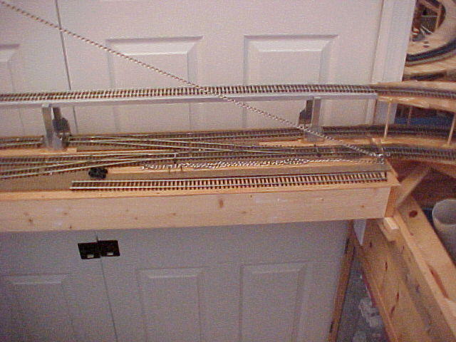
This is the south end of the swing bridge. The top track is part of the main line. The track directly below it is part of the staging track loop. Parallel to that track is the lower portion of the main line.
| Home |
Photo 4 North East Corner
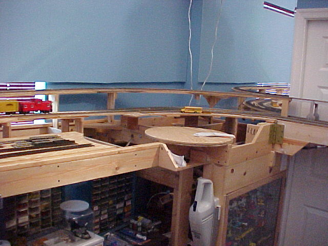
Here you can see the corner of the layout as it approaches the swing bridge from the north. In the lower foreground area, there will be a turntable and an engine service and storage facility.
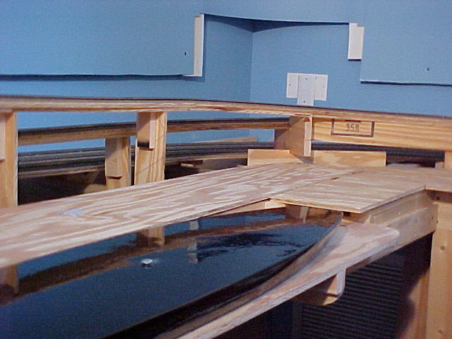
Photo 5 South East Corner
Here you can see the corner of the layout as it approaches the swing bridge from the south. The corner is fitted with a mirror. You can see the upper level main line track and the lower level main line as well. Hard to see and slightly behind the lower level track is the track from the staging yard. In the foreground, you can see the hull of the steamer St. Ignace. It will be a waterline model of a car ferry that worked the Straits of Mackinac in the late 1800's and early 1900's.
The car ferry model hull is made from layers of foam board that have been shaped, filled and coated with black epoxy.
Photo 6 South side and South West Corner
This view shows the wharf area and the hull of the St. Ignace. The upper level track is dropping down and the lower level track is rising to meet it. In the background, you can see the even lower staging tracks. The backdrop is made from foam board attached to firring strips and painted my choice for sky blue.
| Home |
Photo 7 South West Corner - Normal View
In this view, you see the layout from the normal, viewing perspective. It is about 52 inches from the floor to the deck of the car ferry. The other tracks are higher. Most of the staging yard will be covered with lift-out sections of scenery.
Photo 8 West End
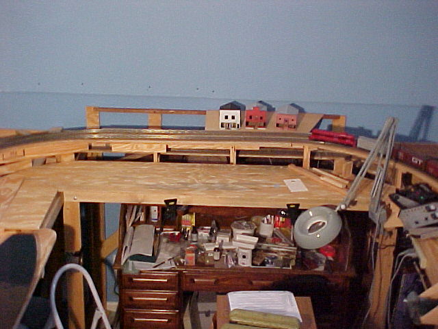
The west end of the layout is the location of the town. For my inspiration, I am working from photos of the town of St. Ignace on the north side of the Straits. I am also using photos of the village of Mackinaw City on the south side (there are many creative ways to spell the name of the area and the natives up there use them all) and of Sutter Creek in California. All three municipalities are currently supported largely by tourist revenues. All three have somewhat similar architecture - some dating from about the same time frame. Many of these buildings predate the estimated 1955 time frame for my railroad and they all seem to have similar character.
At this point, the two parts of the main line loop are level with each other. The staging tracks are covered by the removable town. You can see the beginnings of the buildings that will represent the town. I am using HO kits as my starting point. By adding a foot or so to the foundations and using larger doors, they become S-Scale models. Thank goodness that many HO kits are made a tad oversized.
Photo 9 North West Corner
Here you can see that the outer track is beginning to rise and the inner track to descend. You can also make out the staging tracks below them. My current power is a standard MRC pack and a homemade TAT IV throttle.
Although I have allowed for DCC in the future, I have not yet made up my mind about it. Some recent experiences with DCC on other layouts has convinced me that the case is not clear cut. The sound systems get to be a bit irritating after a few minutes. Also, I have seen numerous instances of unexpected loss of memory in locos and throttles. It all seems to add a layer of complexity that detracts from the railroad experience. It may be that simple block controls will suffice.
Photo 10 North Side
Here is a high view of the north side. The main lines are diverging in height and the staging tracks are rising to meet them on the swing section. Soon, the lead to the wharf area and to the engine service facility will be constructed on the inside of the benchwork.
| Home |
| Site and Pages Copyright 2011-2025 - William P. Porter --- Some content belongs to the indicated provider. |